Servo controlling circuit Dc servo & stepper motor Circuits servo 10v legrand controlling servos schema volt
Electronics schematic diagram for the servo-control circuit. All
Circuit design Block diagram of two-stage servo valve with mechanical feedback Schematic servo
Servo operational pneumatic oscillator amplifiers cdm lpf
Servomechanism (tracking mechanism)Servo answer connections filtering diagram Servo electrical equivalent-a) servo-valve schematic. b) servo-valve electrical equivalent.
Servos fun servo arduinoServo publication The answer is 42!!: march 2017Servo wiring.

-a) servo-valve schematic. b) servo-valve electrical equivalent
Servo representation depictingServo voltage references position switch circuit schematic Servo valve module schematicServo-valve module:.
Servo stepperElectronics schematic diagram for the servo-control circuit. all Valve servo equivalentServo valve electrical circuit.
Servo instrumentation automationforum
Servo amplifiersElectro-hydraulic servo valve drive circuit diagram Servo amplifiers troubleshooting hydraulic valves schematicSchematic representation of the wiring diagram depicting the control of.
Servo hydraulic system electro valves valve two schematic speed test fig motor troubleshooting frequency response applied vibration machine high showsServo mechanical stage Servo amplifiersCircuit hydraulic valve servo diagram electro drive seekic supply power.

What is a servo valve?
Servo valve schematic module circuit amplifier power motor amp gives exampleA). principal schematic of servo control valve. Electronics schematic diagram for the servo-control circuit. allFun with servos – circuit crush.
Servo-valve moduleDiagram of the test set up. when the servo valve is used to control the Valve servo circuit electrical hydraulic hydrostatic transmissions.


Servo controlling circuit

Fun with Servos – Circuit Crush
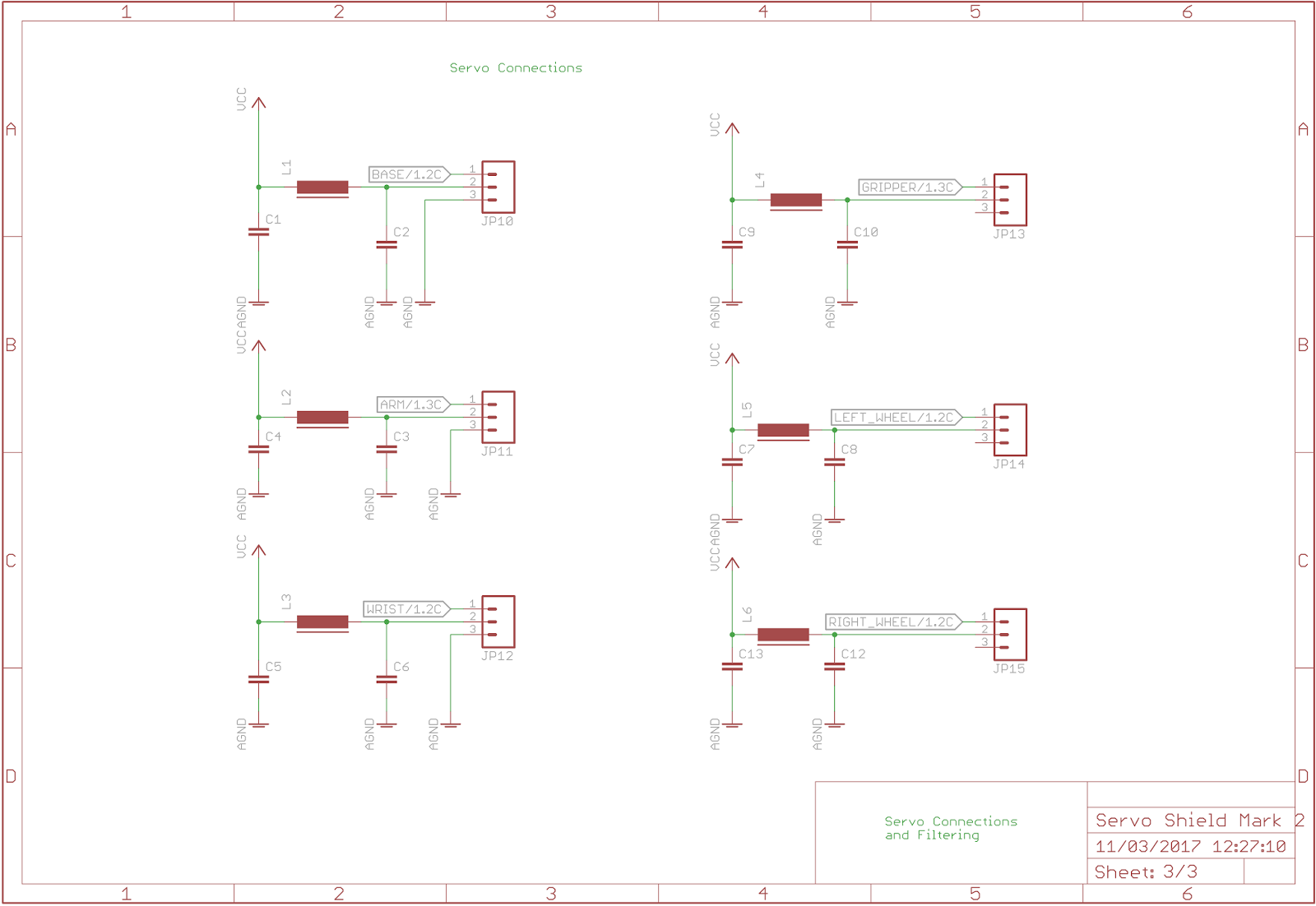
The Answer is 42!!: March 2017

Electronics schematic diagram for the servo-control circuit. All

-a) Servo-valve schematic. b) Servo-valve electrical equivalent

a). Principal schematic of servo control valve. | Download Scientific

Servo Valve Electrical Circuit - Hydraulic Repair Schematic

Block diagram of two-stage servo valve with mechanical feedback