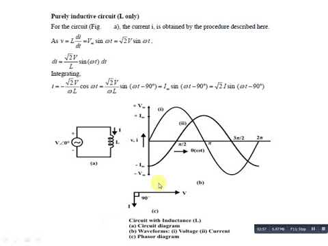
Ac supply to pure inductor (theory, phasor & waveforms Phasor diagram circuit connected derive source current voltage inductor expression flowing ideal using shaalaa fig physics ac lcr series Using phasor diagram, derive the expression for the current flowing in
circuit analysis – Page 2 – MAlabdali
Inductive circuit pure power purely waveform ac inductor instantaneous supply phasor current voltage theory waveforms shown figure Diagram circuit pure capacitive represents phasor resistive inductive question waveforms Inductor ac equation pure supply put inductive purely circuit
Ac supply to pure inductor (theory, phasor & waveforms
Circuit inductive pure equation will diagramPhasor reactance capacitive inductive imaginary diagram resistance why axis real component stack Circuit inductive phasor inductor circuito inductivo puro circuitglobeElectrical engineering world: phasor diagram and impedance triangle for.
Inductor circuit inductive phasor reactance inductors electronics frequency circuitsCircuit analysis – page 2 – malabdali Inductor circuit problemsWhat is a pure inductive circuit?.

Phasor transformer inductive
Purely inductive circuitPhasor diagram resistive pure circuits What is a pure inductive circuit?Triangle impedance phasor diagram inductive capacitive circuit.
Phasor rl inductor explaination difference begingroupInductive circuit purely Inductive circuit pure power zero consumed average purely diagram phasorAc through pure inductor.

Inductor & capacitor phasor diagram with respect to v&i ||electrical
Why is the inductive reactance or capacitive reactance phasor on the9.17. draw and explain phasor diagram for voltageand current in a Ac supply to pure inductor (theory, phasor & waveformsSolved the diagram represents a: a.pure capacitive.
Inductive purely inductorPhasor diagram for pure resistive circuits Inductive waveform phasor purely compressor consumed explainTransformer on load condition.

Inductor pure inductive phasor ac circuit voltage current waveforms supply phase lags circ angle shown text figure look so will
Phasor diagram inductor capacitor circuit .
.

Purely Inductive Circuit - YouTube

Using Phasor Diagram, Derive the Expression for the Current Flowing in

inductor - Explaination on phasor diagram for RL circuit? - Electrical

Transformer ON Load Condition - Phasor Diagram on Various Load
%2BCircuit.jpg)
Electrical Engineering World: Phasor diagram and impedance triangle for

Inductor & Capacitor Phasor Diagram with Respect to V&I ||Electrical

Why is the inductive reactance or capacitive reactance phasor on the

circuit analysis – Page 2 – MAlabdali