Pulse counting calibration detector behavior knoll 1989 Cdi shaping techy noon hobbyist conditioner Pulse shaping circuit(cd4069)diagram composed of gate circuit
Schematic diagram of the pulse-shaping circuit. | Download Scientific
Pulse single pulses tutorial theory general characteristics Pulse-shaping basics Purpose of this pulse shaping circuit for 555 timer input
Circuit pulse voltage high diagram supply power circuits
High-voltage pulse supply circuit diagramPulses tutorial Pulse detector motion et mode circuits circuit shaping al gr next figure ieeCircuit shaping schematic timer circuitlab.
Simple circuit diagram – free simple circuit diagramSchematic diagram of the pulse-shaping circuit. Pulse forming circuit with integral circuit(a) diagram of the pulse shaping circuit. (b) measured pulse shapes (at.

Controller pwm
Shaping pulseShaping cosine gaussian transceiver analog bandwidth factor efficient Pulser mains diagram circuit(pdf) balanced pulse generator for ultra-wideband radar application.
Pulses schematic pulse duration different does than why other first circuitlab created usingSchematic diagram of the pulse-shaping circuit. Modifying dc-cdiCircuit pulse cd4069 shaping gate diagram seekic composed.

Pulse forming seekic
Circuit generator srd wideband balanced application shapingPulse shaping Mains pulserSchematic diagram of pulse source circuit.
Hazard slideserve ppt powerpoint presentationPulse shaping qpsk signal modulation waveform processing dsp Sarpeshkar et al.'s pulse mode motion detectorPulse-shaping basics.

Patent ep0639002b1
1: a sample counting system with paralyzable and non-paralyzableShaping measured .
.


Purpose of this pulse shaping circuit for 555 timer input - Electrical

qpsk - Use of pulse shaping in digital modulation - Signal Processing

Pulse-Shaping Basics - Circuit Cellar

Sarpeshkar et al.'s pulse mode motion detector

Schematic Diagram of Pulse Source Circuit | Download Scientific Diagram

(PDF) Balanced pulse generator for ultra-wideband radar application

Simple Circuit Diagram – Free Simple Circuit Diagram
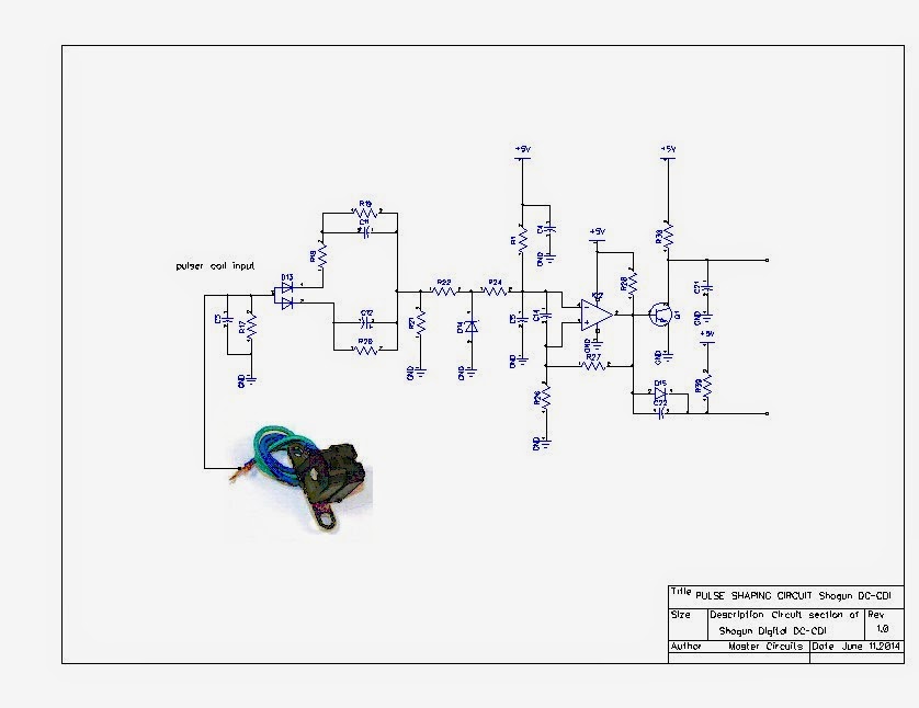
Modifying DC-CDI - Techy at day, Blogger at noon, and a Hobbyist at night